about | articles | authors | contact | links
about | articles | authors | contact | links |
![]() Home > Articles > Fluorescence Photography > Cyan induced infrared fluorescence
Home > Articles > Fluorescence Photography > Cyan induced infrared fluorescence
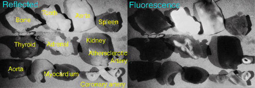
FLUORESCENCE PHOTOGRAPHYAuthors: Prof. Robin Williams and Gigi Williams Cyan induced infrared fluorescenceThe third fluorescence technique of consequence is infrared fluorescence stimulated by excitation wavelengths in the cyan, or blue/green region. Gibson (1962/63) undertook preliminary studies of infrared luminescence of specimens of tissue (Figure 55), but exposures were so long they were impractical and the technique has not therefore found application to the living human subject. Despite the technique's relative inefficiency, it is used in the forensic field particularly in document examination and forgery, where quite dramatic results can be obtained (Creer, 1976).
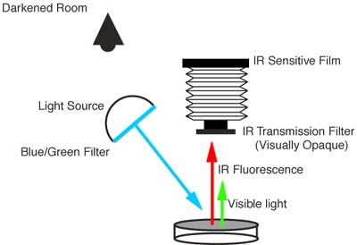
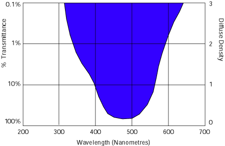
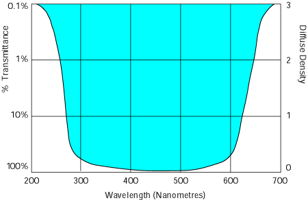
Figure 55 (above). Gibson's experiment to determine the infrared fluorescence (or 'luminescence' as he called it) of a variety of human tissues. The subject was stimulated with light at 480nm and then the infrared emission recorded on Kodak high-speed infrared film. (Larger version). With this technique the subject is illuminated with blue/green light and the fluorescence, which is emitted in the infrared region, is recorded on special infrared sensitive film. Figure 56 illustrates the arrangement for the general technique. The stimulating radiation should ideally peak at 480nm, and the expected emission occurs at 800nm, consistent with Stoke's Law. The ideal excitation filter, therefore, would transmit in the region 400-550nm but would completely exclude any infrared radiation. These filters are not easily obtained, but some of the "heat absorbing" glasses such as the Corning 9780 are suitable. The spectral transmission curve of the Corning 9780 filter is shown in Figure 57. Most researchers in the field have elected to use copper sulphate solution as an exciter filter, eg., Barnes (1958), Godown (1964), Hoover et al., (1964) and Ellen et al., (1970). With this method a perspex tank is constructed and filled with copper sulphate solution. Recommendations vary concerning the concentration to be used but somewhere between 10% and 13% seems correct. Figure 58 shows the spectral transmission curve for the copper sulphate solution at 10% dilution. A much more useful light source, however, is the tunable xenon arc lamp such as the Polilight, Lumilite or Omniprint . With these particular sources, a series of high quality interference filters are rotated into the light beam to achieve narrow pass bands of illumination. One of these pass bands extends from 440nm to 460nm, and so is ideal for stimulating infrared emission.
Figure 56 (above). A diagram for the basic infrared fluorescence technique. The subject is illuminated with light in the blue/green region at approximately 480nm and then stimulated emission of infrared radiation is captured on an infrared sensitive film or CCD. The lens of the camera must be fitted with an infrared absorbing filter and the process must be undertaken in a darkened room.
Figure 57 (above). The spectral transmission curve of the Corning 9780 filter.
Figure 58 (above). The spectral transmission curve for copper sulphate solution at 10% dilution - described by some as the perfect illuminant for stimulating infrared fluorescence. The barrier filter is then a standard infrared absorption filter such as the Wratten 87 or 88A, and the film is usually a high-speed infrared sensitive emulsion. Full details of these filters and films will be found in the section on Infrared Photography. As mentioned above the technique is very inefficient in terms of photons released. Exposed of the order of 2,000 times longer than reflected infrared are not unusual - Creer (1976) reported exposures of four hours duration at f/8 with high-speed infrared film. One method of reducing this problem is the use of photomultiplier tubes. Gains of up to x109 are possible with the modern silicon avalanche photodiodes that have a spectral response from 350nm to 1150nm. Figure 59 shows the arrangement of a multiplier tube for invisible radiation photography. These devices bring infrared luminescence techniques into the practical realm with real time visualisation. The inherent infrared sensitivity of the charged coupled devices installed in digital cameras should also make them suitable for infrared fluorescence work (although they are notoriously susceptible to darkfield noise). Apart from Gibson's initial study, virtually no work has been done to date on the medical and biological applications of this technique.
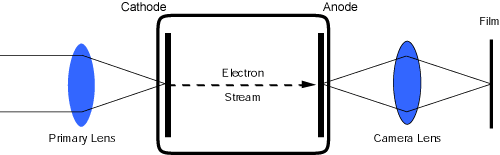
Figure 59 (above). Diagrammatic representation of a photomultiplier tube for invisible radiation photography. The image is in effect 'magnified' in brightness by a cathode ray tube which is then photographed. Gains in effective illumination of several thousand are possible. These devices bring infrared luminescence techniques into the practical realm with real time visualization. References
|
| © 2002 Prof. Robin Williams and Gigi Williams - Disclaimer URL: http://www.medicalphotography.com.au/Article_02/ Last modified: 3 May 2002 |