
about | articles | authors | contact | links
about | articles | authors | contact | links |
![]() Home > Articles > Infrared Photography > Reflected infrared photography: Optical considerations
Home > Articles > Infrared Photography > Reflected infrared photography: Optical considerations
INFRARED PHOTOGRAPHYAuthors: Prof. Robin Williams and Gigi Williams Reflected infrared photography:
|
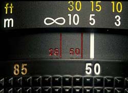 |
Figure 28. The infrared focusing marks often found on modern lenses. Two marks are actually engraved on this lens to represent the range of focal lengths of the zoom. |
Focal length is, strictly speaking, specific to a given wavelength, even different glasses will focus the same wavelengths at different focus points. Chromatic aberration in normal photography has the effect of producing concentric coloured "circles of confusion." Lens manufacturers expend much effort in trying to design combinations of glasses that will effectively eliminate the so-called "chromatic aberration." Crown and flint glasses perform differently with varying wavelengths (see Figure 29), and in practice the lens manufacturer uses these two glasses in such a manner that equal and opposite amounts of chromatic aberration are induced - this process of bringing two or more spectral lines together is called achromatization. Normal lenses are chromatically corrected to cope with a range of wavelengths from 400nm to 700nm. Achromatic lenses have been designed to bring two wavelengths (normally red and blue) into precise coincident focus. Apochromatic lenses have been designed to do the same for three wavelengths (Ray 1988). In the achromatic lens, the red and blue come to focus at the same plane with the curve resembling a parabola. The apochromatic lens focuses three colours on the same plane with the curve resembling a sine wave (Figure 30). The shape of these curves is very important to invisible radiation photography because they show where other wavelengths are likely to fall in relation to the visible focus. Thus, an inspection of the curves shows that with a modern multi-element achromatic lens, the infrared radiation may focus at approximately the same plane of focus as the ultraviolet (Figure 31). In general, it can be seen that the focal length of an achromat increases for infrared, necessitating some correction of focus from the visual point. Depending on its design, the modern apochromat may not need correction for infrared photography.
Figure 29. These curves for crown and flint glass demonstrate that each glass focusses radiation of the same wavelength at different focal points, and that visible light is focussed at a different point from ultraviolet or infrared.
Figure 30. Variation in focal length for different wavelengths, with three types of lenses.
Figure 31. Focus plane curves for a generalised achromat lens and a generalised apochromat lens demonstrate that the infrared image will always focus in a different plane than the visible. Note that it will depend on lens type whether the focus shift for infrared and ultraviolet are in different directions or the same direction.
For critical work, especially at higher magnifications one really cannot rely on the manufacturer's description of the lens and focus tests will be required. This means that some focus shift must be applied after the subject has been sharply focussed by eye in order to obtain sharp results with infrared radiation. The exact amount of shift required will need to be established by testing specific lenses, at specific magnifications. Some workers have tested specific lenses; Clark (1939a), was the first to identify the focus shift caused by chromatic aberration in the infrared and quoted infrared shifts for the then available Kodak lenses, and Freytag (1969) quoted infrared correction values for the Haselblad lens as varying between 0.9 and 0.3%. In an attempt to provide some definitive guidelines for the medical photographer, an extensive series of tests were conducted (Nieuwenhuis, 1991). A test block made of one hundred pieces of 1mm thick card was constructed. Each piece of cardboard was numbered from -50 mm to +50 mm with 0 being in the middle. This block thus provided a test target with a total depth of 100mm in measured 1mm steps. Figure 32 shows a schematic of the test set-up and Figure 33 an actual photograph of such a 'focussing block'. In each case the camera was focussed visually on the zero point in the middle of the block with the expectation that some other step in the block would be recorded sharply, thereby giving a quantification of the focus shift. The aim was to test a practical range of magnifications with various common formats in medical photography. Three formats were selected for testing: 35mm, 120 roll film, and 4 x 5 sheet film. The lenses selected were of the short telephoto variety commonly used for clinical photography. The table below shows the recommended shifts to be applied for black-and-white infrared photography:
| 35mm with 105mm lens | 6x7cm with 135mm lens | 4x5inch with 370mm lens |
| 1:10 - 53mm | 1:10 - 56mm | 1:10 - 0mm |
| 1:8 - 32mm | 1:10 - 44mm | 1:10 - 0mm |
| 1:4 - 8mm | 1:4 - 24mm | 1:4 - 2mm |
| 1:2 - 5mm | 1:2 - 6mm | 1:2 - 3mm |
| 1:1 - 2mm | N/A | 1:1 - 4mm |

Figure 32. A schematic diagram of the focussing block constructed for testing actual focus shifts with different optical configurations.
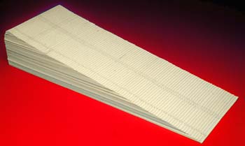
Figure 33. A photograph of the actual focussing block used by the authors.
The application of focus correction can be applied in two ways: either by changing the image distance--moving lens or film plane--or by keeping the camera set at a known magnification ratio and moving the whole camera in relationship to the subject. With large format photography where one has full control of lens and film plane movements, it is easier to apply focus shift to the film plane (Figure 34). For 35mm and roll film formats it is more convenient to move the whole camera. This is best accomplished by using a focussing slide of the kind manufactured for macro photography (Figure 35).
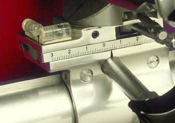
Figure 34. With large format photography it is easy to apply focus shift to the film plane using the calibrated guides.
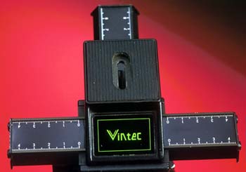
Figure 35. For 35mm a focusing rack calibrated in millimeters is most helpful for applying the focus shift in a practical working situation.
Many lenses that have been corrected for wavelengths in the visible spectrum give an image of poorer quality when used in the infrared range - this occurs even when the optimum infrared focus has been obtained. Diffraction is twice as bad with long infrared wavelengths than it is with short (blue) wavelengths and various diffraction effects have been observed in lenses used for infrared photography. This problem is often made worse by photographers trying to mitigate the effects of focus shift and stopping down in order to get better depth-of-field. Nieuwenhuis, 1990, reported diffraction when using the new style 105mm Micro Nikkor at apertures smaller than f/16. All lenses likely to be used for infrared work should be tested at small apertures for this effect by photographing an evenly lit grey card.
Correct focus with the Ektachrome colour infrared film is virtually impossible to achieve, as one is trying to get infrared, green and red all parfocal. In practice one can only focus normally and rely on depth-of-field for the infrared layer of the image. Alternatively a true Apochromatic lens, or a mirror lens (which is free of achromatic aberration) could be used. Sharper results are actually obtained by making the three negative images separately - green, red and infrared, applying the correct focus shift to the infrared image, and then combining them together in Photoshop (see electronic recording of the infrared image).
| © 2002 Prof. Robin Williams and Gigi Williams - Disclaimer URL: http://www.medicalphotography.com.au/Article_03/ Last modified: 3 May 2002 |