about | articles | authors | contact | links
about | articles | authors | contact | links |
![]() Home > Articles > Reflected Ultraviolet Photography > The practical operating "window"
Home > Articles > Reflected Ultraviolet Photography > The practical operating "window"
REFLECTED ULTRAVIOLET PHOTOGRAPHYAuthors: Prof. Robin Williams and Gigi Williams The practical operating "window"From the previous discussion it is possible to overlay all the spectral transmission or sensitivity curves on a common axis. The result is a harmonization diagram, shown in Figure 52. It demonstrates how the practical window for reflected ultraviolet photography, using conventional films and optics, is from 320nm to 390nm with a peak sensitivity at 365nm. It can be seen that the film is sensitive in this region, the filter and lens both transmit in this region and the xenon flash emits between these wavelengths.
Figure 52 (above). The 'harmonization' diagram for the system components - lens, filter, light source and film shows that the practical operating window for reflected ultraviolet photography is actually between 320nm and 390nm. Recommendations for Practical Working Methods (35mm)
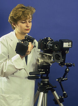
* For those with access to an ultraviolet lens this lens is 1.5 stops faster in the ultraviolet and does not require any focus shift. It is critically important that a standard 'control' image - in colour or panchromatic black-and-white - that represents the visual appearance of the subject, be included as a reference with all scientific invisible radiation records. Obtaining exactly the same viewpoint, with the same lighting can be a very challenging task; this is exacerbated still further when undertaking multi-spectral analysis, where at least three cameras are involved. The authors designed a simple system (Figure 53) where the electronic flash is actually fixed to a tripod and quick release plates fitted to tripod and each camera allow the rapid change over of cameras.
|
||||||||||||||||||||||||||||||||||||||||||
| © 2002 Prof. Robin Williams and Gigi Williams - Disclaimer URL: http://www.medicalphotography.com.au/Article_01/ Last modified: 3 May 2002 |