about | articles | authors | contact | links
about | articles | authors | contact | links |
![]() Home > Articles > Reflected Ultraviolet Photography > Optical considerations
Home > Articles > Reflected Ultraviolet Photography > Optical considerations
REFLECTED ULTRAVIOLET PHOTOGRAPHYAuthors: Prof. Robin Williams and Gigi Williams Optical considerationsFocal length is, strictly speaking, specific to a given wavelength, even different glasses will focus the same wavelengths at different focus points. Chromatic aberration in normal photography has the effect of producing concentric coloured "circles of confusion." Lens manufacturers expend much effort in trying to design combinations of glasses that will effectively eliminate the so-called "chromatic aberration." Crown and flint glasses perform differently with varying wavelengths (see Figure 33), and in practice the lens manufacturer uses these two glasses in such a manner that equal and opposite amounts of chromatic aberration are induced - this process of bringing two or more spectral lines together is called achromatization.
Figure 33 (above). Crown and flint glasses bring the same wavelengths to focus at different points. In practice the lens manufacturer uses these two glasses in such a manner that equal and opposite amounts of chromatic aberration are induced allowing most of the visible spectrum to be sharply focussed at one 'compromise' point. The ultraviolet point of sharp focus often lies outside this 'achromatic' compromise range.
Figure 34 (above). Achromatic lenses have been designed to bring two wavelengths (normally red and blue) into precise coincident focus. Apochromatic lenses have been designed to do the same for three wavelengths. The shape of these curves is very important to invisible radiation photography because they show where other wavelengths will focus in relation to the visible focus. Thus, an inspection of the curves shows that with a modern multi-element achromatic lens, the ultraviolet may focus at approximately the same plane of focus as the infrared whereas with the apochromat the infrared and ultraviolet focus shifts will be in opposite directions. Normal lenses are chromatically corrected to cope with a range of wavelengths from 400nm to 700nm. Achromatic lenses have been designed to bring two wavelengths (normally red and blue) into precise coincident focus. Apochromatic lenses have been designed to do the same for three wavelengths (Ray, 1988). In the achromatic lens, the red and blue come to focus at the same plane with the curve resembling a parabola. The apochromatic lens focuses three colours on the same plane with the curve resembling a sine wave. The shape of these curves is very important to invisible radiation photography because they show where other wavelengths are likely to fall in relation to the visible focus. Thus, an inspection of the curves shows that with a modern multi-element achromatic lens, the ultraviolet may focus at approximately the same plane of focus as the infrared (Figure 34). In general, it can be seen that the focal length of an achromat increases for both ultraviolet and infrared, necessitating some correction of focus from the visual point. The ultraviolet shift for a modern apochromat - or indeed 'old' non-achromatic lens will be in the opposite direction to that of infrared. For critical work, especially at higher magnifications one really cannot rely on the manufacturer's description of the lens and focus tests will be required. In a normal lens, wavelengths shorter than 400nm, or longer than 700nm, are brought to focus away from the optimised point of visual focus. The difference in distance between the visible focus and either the ultraviolet or infrared focus is known as the "focus shift" and unless some correction is applied, unsharp photographs will result - particularly at the magnification ratios typically used in biomedical photography. Figure 35 clearly demonstrates that unsatisfactory results are obtained with conventional lenses when some compensation is not made for chromatic shift.
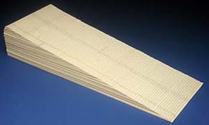
Figure 36 (above). A schematic diagram of a focussing test block constructed with equal steps of 1mm used to experimentally test the focus shift of individual lenses at different magnifications. Various approaches have been taken in the past to solve the focus shift problem. In the case of ultraviolet photography, many have relied on depth of field to cope with any change in focal distance (Kodak publication; M-27, 1987), or on the use of a ground-glass screen coated in a fluorescent compound such as "anthracene" which enables one to see a visible fluorescent image of the otherwise invisible ultraviolet one (DeMent and Culbertson, 1951). An alternative solution has been the use of a teleconverter tube, which is sensitive to ultraviolet, mounted to look at the focussing screen of the camera (Mustakallio and Korhonen, 1966). When using the reflected ultraviolet technique, some workers have even advocated moving the lens barrel by the same amount as the infrared mark, but in the opposite direction (West et al., 1992). Unfortunately, this produces the opposite of the required result in many modern achromatic lenses. All of these methods have shortcomings and are not accurate enough for the medical photographer who often works at close range. Depth of field, for instance, compensates for some change in focal distance but experience shows that even at quite small apertures, the shift in focal point for ultraviolet wavelengths causes out of focus results and some compensation must be applied. In a simple lens, theory suggests that a decrease in the lens to image distance would be required for ultraviolet and an increase for infrared. However this is not the case for a compound lens which has been achromatized, and focus shift for ultraviolet may be in the same direction as that required for infrared photography. Individual lenses must be tested. In an attempt to provide some definitive guidelines for the medical photographer, an extensive series of tests were conducted (Nieuwenhuis, 1991). A test block made of one hundred pieces of 1mm thick card was constructed. Each piece of cardboard was numbered from -50 mm to +50 mm with 0 being in the middle. This block thus provided a test target with a total depth of 100mm in measured 1mm steps. Figure 36 shows a schematic of the test set-up and Figure 37 an actual photograph of such a 'focussing block'. In each case the camera was focussed visually on the zero point in the middle of the block with the expectation that some other step in the block would be recorded sharply, thereby giving a quantification of the focus shift. The aim was to test a practical range of magnifications with various common formats in medical photography. Three formats were selected for testing: 35mm, 120 roll film, and 4 x 5 sheet film. The lenses selected were of the short telephoto variety commonly used for clinical photography.
Figure 37 (above). A photograph of a focussing test block. The application of focus correction can be applied in two ways: either by changing the image distance--moving lens or film plane--or by keeping the camera set at a known magnification ratio and moving the whole camera in relationship to the subject. With large format photography where one has full control of lens and film plane movements, it is easier to apply focus shift to the film plane (Figure 38). For 35mm and roll film formats it is more convenient to move the whole camera. This is best accomplished by using a focussing slide of the kind manufactured for macro photography (Figure 39).
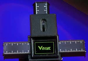
Figure 38 (above). Applying focus shift to the film plane is relatively easy with large format photography where one has full control of lens and film plane movements - often, as with this Sinar Camera - having access to graduated scales.
Figure 39 (above). For 35mm and roll film formats it is more convenient to move the whole camera. This is best accomplished by using a focussing slide of the kind manufactured for macro photography. Table 1 - Required focus shifts for ultraviolet photography with modern achromats. Move the whole camera back by the following amounts:
Table 1 provides the shifts required for ultraviolet at various magnifications using the above techniques. Once visually focussed, the whole camera can then be moved back on a focussing rack according to the distances in the table. These tables should provide helpful recommendations for the practicing professional photographer but it must be kept in mind that complex lens designs behave in unpredictable ways, and if the ultimate in precision is required, specific lenses should be tested at the magnifications and wavelengths at which they are to be used. When selecting lenses for short wavelength photography, it is important to consider the transmission limits for the various materials that might be encountered. Optical glass, for example, starts to absorb ultraviolet around 320nm. The band from 120nm to 200nm is sometimes called the Schumann region, and is the shortest waveband in which refractive lenses (usually fluorite) can be used. The practical "window" for photography with normal lenses therefore extends from about 320nm to 390nm. It is, for this reason, that photography is mostly confined to the near, or UVA, region. Many lenses have good transmission (30-50%) at 365nm, although this should not be taken for granted, especially with modern multi-element lenses. At one time specialty lenses were manufactured for ultraviolet photography, principally, those that were available from Nikon, Hasselblad, Pentax and Carl Zeiss, and these transmitted ultraviolet down to 200nm. Regrettably, once again the specialised nature of these products has meant poor sales and they are now all withdrawn. Many large scientific or medical photography departments however still have access to such lenses. The Carl Zeiss UV Sonnar was designed for the Hasselblad medium format camera; it is a 105mm lens with a maximum aperture of f/4.3 and an efficient transmission down to less than 300nm. (One of these was recently for sale on the web for $15,000). The Pentax lens is made from fluorite and quartz elements, and has a focal length of 85mm and maximum aperture of f/4.5. It is designed for the 35mm film format, and has an aberration free range from 220nm to 1000nm. (Note some so-called "UV lenses" the UV Topcor , for example, were specifically designed to exclude the near ultraviolet). The UV Nikkor was probably the most popular of the "ultraviolet" lenses. It looks exactly like a 105mm Micro-Nikkor lens, and is marked out in the magnification ratios familiar to biomedical photographers. The lens elements are manufactured from fluorite and quartz, and this allows a spectral transmission as high as 70% from 300nm to 900nm (Figure 40). This means about one and a half stops more ultraviolet transmission in the 300nm to 400nm region than the standard 105mm Micro-Nikkor . Another major advantage is that the lens is manufactured deliberately so that green and ultraviolet radiations are brought to a focus at the same point over a wide range of magnifications. Thus, there are no achromatic focus shift problems when using this lens for ultraviolet photography. It also provides very good resolution because the aberrations are principally corrected for the ultraviolet region. The lens came ready fitted with a flip down filter holder containing Nikon's own equivalent of the Wratten 18B filter (Figure 41). The one disadvantage, however, was always cost. When the lenses were last listed (1993) the lens cost $3,700 in the US and £1,700 in the UK.
Figure 40 (above). The spectral transmission curves for the popular Nikon Micro-Nikkor 105mm lens and its now defunct but very special 'UV brother'.
Figure 41 (above). The spectral transmission curve for Nikon's proprietary filter fitted to the UV Micro-Nikkor is very similar to that of the Wratten 18B. References
|
||||||||||||||
| © 2002 Prof. Robin Williams and Gigi Williams - Disclaimer URL: http://www.medicalphotography.com.au/Article_01/ Last modified: 3 May 2002 |